The 'Kitsilano' Oscillator Circuit
==================================
Introduction
------------
**Kitsilano** is an oscillator circuit based on two NPN transistors and
a single capacitor. It is so named because it is the most interesting
circuit (really, the only significant circuit) that I designed while I
was living in the Kitsilano neighbourhood of Vancouver, British
Columbia, Canada. Its design was a byproduct of a quest which I have
since recognized as futile, and abandoned: the design of a
single-transistor, inductor-less oscillator. The pursuit itself was
somewhat interesting though, so I'll tell you about it in the next
section. In the third section, I'll describe the Kitsilano oscillator
itself.
1Q0L
----
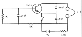
Figure 1. A single-transistor (and apparently inductor-less) oscillator.
(From [Sessions 1975](#references)).
The notion of a single-transistor oscillator, built without an inductor,
tantalized me for a while after I came across what looked like such a
circuit in a book of somewhat older circuits that I checked out from the
public library ([Sessions 1975](#references)). It is shown in Figure 1. It clearly
contains only one transistor and no coils, and the caption claims that
the tone it produces, though not loud, is adequate for keying (that is,
Morse code) practice. Further, the circuit is organized in a way that
coincides with my understanding of how one might go about eliminating
the inductor from a Colpitts oscillator: by replacing it with a
capacitor and a resistor in parallel and in series with another
resistor, an arrangement which can be thought of as a very rough
equivalent to an inductor.
However, every attempt I made at building it failed to produce any
results. It was not until much later that I came up with a plausible
theory for why it didn't work. The audio output in this circuit was
shown as a pair of headphones labelled "Hi-Z". This means
"high-resistance", and indicates old-style *piezoelectric* headphones
rather than the more modern magnetic-coil speakers. What took me so long
to realize is that piezoelectric elements are crystals, and *crystals
provide inductance* (which is why they can be used in crystal
oscillators!) In this circuit, the headphones are apparently a critical
component which acts as an inductor in the oscillator. I haven't been
able to hunt down a genuine crystal-element earpiece yet, so I haven't
been able to test this theory, but it's the best idea I've come up with
yet for why it doesn't work without one.
The Design of the Kitsilano Oscillator
--------------------------------------
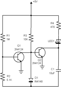
Figure 2. The 'Kitsilano' Oscillator Circuit.
Having given up on a single-transistor, inductorless oscillator, and
discovering in other library books several single-transistor,
one-inductor designs (such as the Colpitts oscillator), I concentrated
my efforts on designing a two-transistor, no-inductor oscillator.
I had encountered several two-transistor designs previously. One is the
"multistable multivibrator", which uses two transistors of the same
type, and two capacitors. Each transistor-capacitor pair acts as a timer
which triggers the other pair when it has discharged. Another design
involves only a single capacitor, but two transistors of complimentary
type (NPN and PNP.) Many circuits based on both of these oscillator
designs can be found in [Mims 2003](#references).
Well, what I wanted was an oscillator built from two transistors of the
*same* type, but incorporating only *one* capacitor. This effort
resulted in Kitsilano.
The theory of Kitsilano's design was adapted from a fairly standard
oscillator design that utilizes two CMOS inverters. This is usually
implemented with half of a 4001 chip (tying the inputs of each NAND
together to form an inverter.). One of the inverters is fed its own
output through an RC circuit, and the other inverter is used to
stabilize the feedback and "square off" the output. Circuits
incorporating this oscillator design can also be found in
[Mims 2003](#references).
(In fact, it's not required that such an oscillator be constructed from
CMOS gates. [This figure](2NOR_oscillator.png) shows a circuit along the
same lines that I built from LSTTL NOR gates, driving a
series-resistor-less LED via a transistor. Measuring the current usage
shows why CMOS is preferable: LSTTL uses a lot.)
Kitsilano uses the fact that **an inverter can be built with a single
transistor** to replace the two CMOS inverters with two transistors of
the same type. The remainder of the circuit is officially a hack, since
it was designed "by dint of sheer building." The circuit is depicted in
Figure 2.
For the construction itself, I chose two 2N4124 transistors — they're
NPN and they're about as cheap as they come. The requisite task of an
oscillator, as far as I'm concerned, is to blink an LED, so I chose C1
large enough to make this action visible to the unaided eye.
R1 was not originally part of the circuit: there was no connection
between Q1's base and +5V. This oscillator would oscillate sometimes,
while at other times would fail to oscillate. I eventually discovered
that it was very sensitive to where my hands were placed above or around
the circuit, so I added to the high-resistance path to +5V to make sure
there was always some voltage at Q1's base, making its behaviour more
stable.
D1 was originally a resistor (I forget the ohmage.) The circuit worked
fine with a resistor there, but I wanted something stranger, so I
experimented with replacing it with a diode. This worked too, although I
cannot quite tell you why (does the voltage drop across the diode serve
the same function as the resistance?) so I kept it in.
References
----------
1. Kendall Webster Sessions, ed. *Master handbook of 1001 practical
electronic circuits.* Blue Ridge Summit, Pa. : G/L Tab
Books, 1975.
2. Forrest Mims III. *Getting Started in Electronics*. Master
Publishing, Inc., 2003. ISBN 0945053282.